LAUGHTON ELECTRONICS |
|
Between a rock and a hard place: the ReelTech breakdown |
|
 |
This article describes the sort of repair job that's my unique specialty: a valuable (but broken) machine that's an "orphan." Faced with that sort of situation, there aren't many places the owner can go for help. But this story has a happy ending. The solution was found after some wire tracing and after reverse-engineering some computer code in order to smoke out the problem. |
|
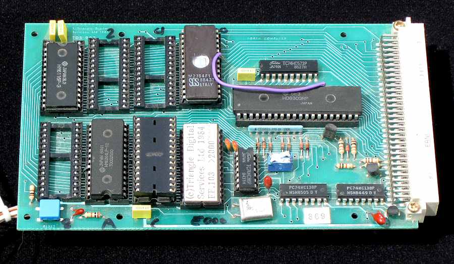
The day the ReelTech broke down is a day my client would probably prefer to forget. When this machine suffered an malfunction it crippled their operation, and something had to be done. But there was little comfort to be found when they contacted the manufacturer overseas. The machine was a semi-custom unit, built over ten years previously. Because there was no documentation on file the manufacturer declined to attempt a repair. They apologetically suggested that the solution might be to tear out all the control wiring and install some sort of updated replacement! Or, a new machine could be put on order for about $100k, eventually to be shipped across the Atlantic before finally being installed. Needless to say, neither proposal was appealing, so the client made some alternative inquiries and was relieved at last when I agreed to deal with the situation. the "patient"The ReelTech is a laminating machine, about 18 ft. long, used to produce adhesive-backed paper labels for retail and commercial needs. The printed label material, usually produced on a web press, feeds off a large roll. The ReelTech applies a transparent laminate that's fed from a second roll. It then makes die-cut perforations that separate the individual labels, and finally it cuts the finished product into sheets. The control system, housed in a card cage, includes a microprocessor board, power supply and about a dozen interface boards. Remote equipment includes numerous sensors and switches, an encoder and motor controller for the transport, and the Operator's Control Panel, which includes more switches and some 7-segment LED readouts. Regarding the interface boards, it happened that the client had spares for a few of them, but swapping in the spares made no difference. That wasn't surprising, but still it's important be aware of all the dumb, easy stuff you can do first, and to try to avoid immediately diving into Sherlock Holmes mode. the symptoms and the diagnosisThe system appeared to power up normally, but when the Start button was pushed the drive motor refused to actuate — except for a momentary tremor. This suggested that transient electrical noise created by the motor startup might be a factor, but it didn't reveal where the supposed noise, if any, was getting picked up. I prefered an approach where I could trace step by step, and I decided more exploring was in order. I'd learned a lot by tracing the machine wiring, including the basics of the 6303 microprocessor card and of two associated 6820 parallel interface cards. One of the parallel ports was what ran the Operator's Control Panel. But the wiring didn't really tell the story, because so much of the machine's behavior was determined by the microprocessor's program. I undertook to get a grasp of the mystery software. It was easy enough to remove the two 2764 program EPROMs and to copy the contents onto my personal computer. Then I spent over a week reverse engineering parts of the code — 16 kilobytes of unknown code for the undocumented machine! This was partly a pencil-and-paper effort, with notes jotted down earlier regarding IO devices whose addresses I'd been able to identify, and what their various bits seemed to be for. There was also some automated searching: if an address, either of a device or routine, seemed pertinent I'd do a search in the object code for references to that address. As with a jigsaw puzzle, I eventually found I was dealing with some moderately big chunks. I was aided by the happy coincidence that the application code was compiled in F.I.G. Forth, with which I was already familiar and comfortable. The next phase was some live testing. I'd figured out how to add a code patch that spit out trace dumps to an RS232 terminal, and with this setup I could step into successively deeper levels of subroutines as the machine ran its startup sequence. It was painstaking work, but eventually I found myself examining the results of a routine whose purpose was to report the status of a certain switch. There were many such routines, all identical except regarding which bit of which I/O port got tested. But in this case it was the machine Stop switch being interrogated, and the subroutine reported that the Stop switch was pressed when in actual fact it wasn't. Here at last was the smoking gun! The problem turned out to be internal to one of the interface boards in the card cage. Although the Stop switch signal tested OK where it entered the card, a faulty opto-coupler IC meant the data got stomped before it ever reached the microprocessor bus. From the computer's point of view, the Stop switch was always saying stop! As for the momentary tremor in the motor as the machine tried to start, this was not electrical noise but an artifact of the very odd way the program was written. It actually began by polling the Start switch then issuing the start command to the motor controller and dropping into a loop for run mode. At the bottom of the loop it'd poll the Stop switch to see whether to loop again. Only after exiting the loop would the command to the motor controller would get canceled. The elapsed time — thanks to the sluggish 6303 processor — was long enough to produce a reaction in the motor. Replacing the opto-coupler put the machine — and my grateful customer — back in business. |
|
|
")
|
|