LAUGHTON ELECTRONICS |
|
a system of Safety Interlocks is retrofitted to existing equipment |
|
 |
Increasingly strict safety standards are an issue of concern to employers. Government inspections make the matter impossible to ignore. This article describes how a valuable piece of equipment was upgraded to meet modern requirements. |
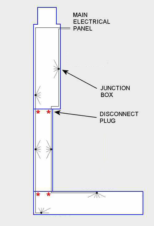
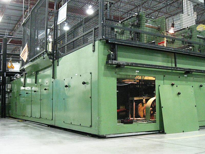 Kugler with a panel open. * Click to expand any image. *
The trunk lines run
along the perimeter, linking the
|
This book-binding machine, made in Germany about 20 years ago by Kugler Automation, is central to one of my clients' operation. Therefore it was a serious matter when the Ontario Ministry of Labour gave notice that there was a problem with safety. The machine needed to be upgraded or replaced — or else it would be shut down and locked out. Replacing the machine was out of the question, so I was asked to plan and install a system of safety interlocks. The machine is about 10 meters long (over thirty feet) and has a series of removable panels close to floor level. Behind the panels are the shafts, gears and cams that drive the various reciprocating components at each station. Obviously these mechanisms are potentially dangerous. My job was to arrange for the machine to stop automatically if any of the panels was opened. This "simple" concept entailed some detailed considerations. These include:
Switch SelectionBecause a tamper resistant switch was required I selected Omron's type D40A for the project. This switch is two-piece "non-contact" type, with a solid-state sensor that mounts on the chassis and a magnetic actuator that can attach to a door or panel. The sensing range (sensor to actuator) can be as much as 1 cm, which helps to overcome any minor mis-alignment that may exist with the Kugler panels. The panels hang, somewhat sloppily, on hooks (as shown in the photo). The aluminum parts behind the actuator serve to locate it adjacent to the sensor. Also, the sensor itself mounts on a 1/8 inch aluminum shim. This reduces proximity to the machine's steel frame — a ferrous object which might otherwise interfere magnetically, reducing sensing range and increasing the likelihood of a false alarm.
Cable Harnesses and signal multiplexingAdding extra cabling to this machine was problematic. The wiring conduits were already stuffed close to capacity, and in any case it would be absurd to try to run 29 individual switch wires back to the electrical panel. The situation required a series of secondary nodes where individual switch wires could connect to a trunk line. Six "junction boxes" are the nodes that serve this function. Each junction box has a maximum of six switches connected to it.It was important that the trunk cable itself be minimized. For example, it would be undesirable to run a fat, 29-conductor cable through the machine — due to space limitations, and also because that would entail 29-pin disconnect plugs. (Disconnect plugs allow the machine to be partially disassembled in the event of its being moved.) Instead, the plan uses a pair of much thinner cables: only three conductors, plus a few D40A specific signals. These cables run along the outer and inner perimeter of the machine, as show in the diagram (above left). The reduced conductor count in the trunk cables is achieved by signal multiplexing. Specifically, each junction box requires just a single conductor to transmit the state of all six switches attached to it. Nevertheless, the circuitry in each junction box is delightfully simple, thanks to an original analog encoding scheme. Each switch is associated with a unique voltage, determined by a zener diode that connects it to the analog bus for that box. Multiple switches active on the same bus do not mutually interfere because all the zeners are individually current-limited to a known value (3.5 mA, which also conveniently powers each switch's setup LED). The controller, located in the main electrical panel, tests voltage and current in order to discriminate between signals on the analog buses. The remaining four conductors in the trunk cables are for 24V power and for a signal loop used by the D40As. The loop is managed by an Omron G9SX (a D40A accessory). It's capable of detecting wiring faults in the loop, such as tampering or a short to +24 — a hazard which might prevent recognition of an open- panel signal. The G9SX, located in the main electrical panel, is what triggers the actual machine stop circuit. Its output is just a simple Go / No-Go decision. The multiplexed signals operate independently, using the Auxiliary output on each switch. This is what identifies individual switches in order to support the Human Interface (signal system). Human Interface (signal system)The project includes a large, conspicuously-mounted LED lamp on a pole. Its function is to inform staff which switch has been triggered. Although it's usually obvious when a panel is open, the signal acts to identify invisible real-world glitches such as a switch or actuator that has gotten knocked out of alignment, yielding a spurious machine stop. Thus it is a means of minimizing machine down time — always critical in a production environment.To indicate which switch has been triggered, the LED lamp blinks out the necessary information. For example, 2 flashes followed by 6 flashes would indicate that switch 26 has been triggered. The system can manage any combination of panels open simultaneously. Multiple panels open simply result in multiple flash codes in succession. Alternative or additional signalling can easily be arranged since an industry-standard 24V PLC interface is provided. One PLC output and two PLC inputs are required (clock, data & strobe, respectively). But hookup to an external PLC is strictly optional. Typically the system is self-contained, relying on the microprocessor inside the controller and driving the LED lamp directly. ConclusionThis is a project that leverages the client's capital investment by extending the useful lifetime of the machine. Assemblies, code and full documentation are available. |
|
|
") |
|